|
|
|
|
مواقع
مفضله
The
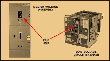
second type of trip unit is the electronic trip unit. It is generally
temperature insensitive and more expensive. It is used on low voltage circuit
breakers beginning at 400A and on medium voltage circuit breakers. The trip unit
is integrally mounted on the low voltage and externally mounted on the medium
voltage. Figure 22. Electronic
Trip Units This
unit is rapidly replacing the thermal magnetic trip because of its increased
accuracy, repeatability and discrimination. It also has an optional built-in
ground fault protection. In addition, it offers other capabilities such as
programming, monitoring, communication, system coordination and testing. In
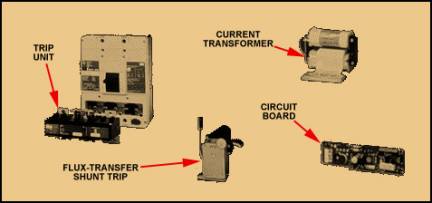
general, electronic trip units are composed of three components, which are
internal to the trip unit. These components are the current transformer, circuit
board and flux-transfer Shunt
Trip. Figure 23. Components
of Electronic Trip Unit
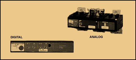
There
are two types of electronic trip units: Analog and Digital. Figure 24. Digital and
Analog Trip Units The
analog trip unit was developed first and
considered the conventional approach. It functions
by looking at all the points on a particular curve and responding to peak
values. This can cause a problem because peak sensing can cause false
tripping. The unit is also sensitive to harmonics. Figure 25. Analog Peak
Sensing The
digital trip unit functions by looking
at selected discrete points on a particular curve and making a summation of
those discrete points. The result is an RMS
value that is more accurate because you are using all of the values
instead of just peak values. This method correlates better with the thermal
characteristics of conductors and equipment. Figure 26. Digital
Peak Sensing
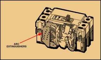
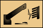
An
Arc
Extinguisher
is the component of the circuit breaker that extinguishes an arc when the
contacts are opened. An arc is a discharge of electric current crossing a gap
between two contacts. Circuit breakers must be designed to control them because
arcs cannot be prevented. There are four techniques to extinguish an arc and
there are several arc control methods. In this topic, you will be introduced to
those methods. Figure 27. Arc
Extinguishers
The
arc is defined as a discharge of electric current
crossing a gap between two contacts. Arcs
are formed when the contacts of a circuit breaker are opened under a load. Arcs
can be very destructive and vary greatly in size and intensity. The
size of the arc depends on the amount of current present when the contacts are
pulled apart. For example, an arc that forms when normal load current is
broken is insignificant compared to the arc that forms when a short circuit is
broken. Because arcs cannot be prevented, circuit breakers must be designed to
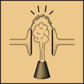
control them. The
heat associated with an arc creates an ionized gas
environment. The more ionization, is the better conditions for the arc to be
maintained and grow., the more heat created,
increases ionization. The
important thing to remember here is that the ability of
the circuit breaker to control the arc is the key to its short circuit
interrupting capability. This is a critical factor for selecting circuit
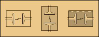
breakers. A
short circuit is the most devastating overcurrent condition.Current
Zero or Zero
Point is a very important aspect to arc extinguishing. At
current zero, conditions are optimal for preventing an arc from continuing.
The current is said to be "Current Zero" when the sine curve is at 0°,
180° and 360°. Figure 29. Current Zero Voltage
is also a very important consideration because it is the pressure that keeps the
current moving. Circuit breakers take this process into account by simultaneously opening the contacts and extinguishing the arc. The successful extinguishing of the arc depends on the Dielectric Strength of the gap between the contacts. The dielectric strength is the maximum voltage a dielectric can withstand without breaking down. A Dielectric is any insulating material between two conductors. In these discussions, the circuit breaker contacts are the conductors and the insulating material can be air, gas or a vacuum. If the dielectric strength is greater than the voltage trying to re-ignite the arc, the arc extinguishing will be successful. Figure 30. Extinguishing an Arc
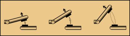
Each
approach has made improvements to its initial concept in an effort to extinguish
arcs more efficiently. Arc control methods utilize one or more of the following
general techniques:
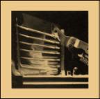
Figure 31. Stretching
Arc
Figure 32. Breaking
Arc
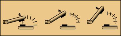
Figure 33. Blowing Out
Arc
Figure 34. Enclosing
Contacts
There
are six methods used around the world today to deal with arc control. The two
most commonly used methods are arc chute and vacuum interrupter. The other four
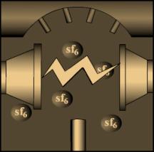
methods are SF6, minimum oil,
magnetic coil and puffer.
Figure 35. Arc Chute
Method
Figure 39. Puffer
Method As you have seen, there are several techniques to effectively deal with extinguishing arcs and improvements continue to be made.
BACK HOME SWICHING DEVICES MENU
|
|
تصميم المهندس : محمد صبري محمود فهيم إستعداد تام لتصميم المواقع إستعداد تام للعمل داخل أو خارج مصر E-Mail: Mohamedmsm@Masrawy.com |